
The Firefly Mini board
Over the years, I’ve worked on countless electronics projects, often making my PCBs by hand and prototyping with breadboards and Dupont wires. One of the biggest headaches I faced was dealing with unreliable connections—whether it was sketchy PCBs or those pesky Dupont connectors that loosen after a few uses, causing intermittent issues. Living by the ocean added another challenge: corrosion, which only made things worse.
A few years ago, I noticed that many of my projects shared similar requirements. That’s when I decided to design a small PCB specifically for my Wemos D1 Mini projects. This board had several advantages: screw terminals for secure connections, a direct plug-in for an OLED display, two push buttons, an IR receiver, and support for a 2-channel 5V relay module. With this setup and the right firmware, I could build a variety of devices on the same board.
The Firefly Mini is a compact, reliable, and incredibly useful board that can simplify your projects and eliminate the frustrations of bad connections. I hope you find it as helpful as I have!
Description
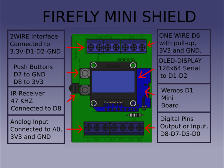
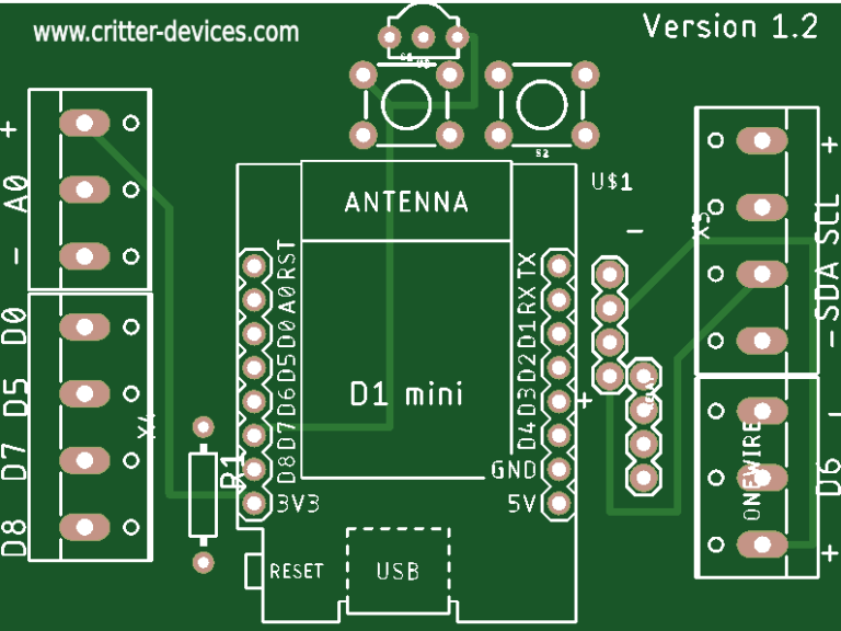
The Firefly system maps the pins of the Wemos D1 Mini board to screw terminal connectors on the main board, providing easy access and connectivity. In addition it provides female connectors for a SD3106 OLED display, 2 push buttons and an IR sensor.
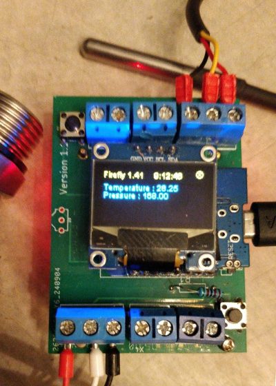
Example of application
The picture shows a Firefly Mini with a analog pressure connected to the analog terminals ( bottom left ) and a DS18B20 temperature sensor connected to the onewire terminal ( top right )
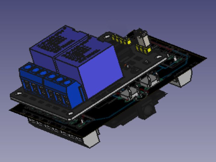
Relay Board Addition
One hidden feature of the Firefly Mini board is the possibility of attaching a 2 channel 5 volts relay board on the back of it. The relay board needs a slight modification to fit this configuration, it just involves heating up and pushing down the 4 input pins so they face the opposite side of the PCB and they can serve as a bridge between the 2 boards. The relay terminals are routed to pins D3 and D4.
Copyright. All rights reserved.
Necesitamos su consentimiento para cargar las traducciones
Utilizamos un servicio de terceros para traducir el contenido del sitio web que puede recopilar datos sobre su actividad. Por favor revise los detalles en la política de privacidad y acepte el servicio para ver las traducciones.